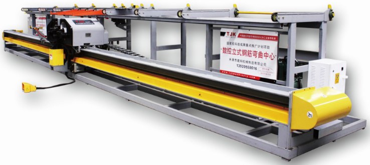
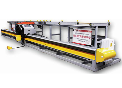
Features of Rebar Bending Line G2L25X (10-25 mm)
 |
Rebar Bending Line G2L25/G2L32E-2(bar benders) has advanced technology is introduced from Europe, lots of parts have patent for invention, the high efficiency also high endurance and humane designings are safe and reliable; |
| High precision of PLC control, it is powerful database inside,no need manual adjustment; |  |
 |
Rebar Bending Line G2L25/G2L32E-2(bar bender machine) is precisely working with angle, maximum diameter for bending is 60mm; |
| Rebars can be bent by double-shaft, workable of direction from forward and reverse; More than one rebars can be bent at the same time,bending range 0°-180°; the service life and efficiency are greatly improved by the bending units which made by special materials;the workers safety are ensured by the covering of the machine(bar benders); |  |
 |
TJK Rebar Bending Line G2L25/G2L32E-2(bar benders) have been sold more than 300 pcs around the world. |
Characteristics of Rebar Bending Line G2L25X
Rebar Bending Line G2L25/G2L32E-2(bar benders) has advanced technology is introduced from Europe, lots of parts have patent for invention, the high efficiency also high endurance and humane designings are safe and reliable;
High precision of PLC control, it is powerful database inside, no need manual adjustment;
Rebar Bending machine Line G2L25/G2L32E-2(bar bender machine) is precisely working with angle, maximum diameter for bending is 60mm;
Rebars can be bent by double-shaft, workable of direction from forward and reverse;
More than one rebars can be bent at the same time,bending range 0°-180°;
The service life and efficiency are greatly improved by the bending units which made by special materials; the workers’ safety is ensured by the covering of the machine(bar benders) ;
TJK CNC Rebar Bender G2L25/G2L32E-2(bar benders) have been sold more than 300 pcs around the world
Technical Data of Rebar Bending Line G2L25X
| TECHNICIAL DATAModel | G2L25 | G2L32E-2 | ||||||||||||||
| Bending capacity | Clockwise and Anti-clockwise:Φ10 – Φ20 [mm] Single direction: Φ10 – Φ32 [mm] |
Clockwise and Anti-clockwise: Φ10 – Φ25 [mm] Single direction: Φ10 – Φ32 [mm] |
||||||||||||||
| Max. bending angle | clockwise: 120° anti-clockwise: 180° |
clockwise: 120° anti-clockwise: 180° |
||||||||||||||
| Max. bendingside length | 10 [m] | 10 [m] | ||||||||||||||
| Min. bendingside length | Φ10mm 450mm | 700 [mm] | ||||||||||||||
| Φ25mm 500mm | ||||||||||||||||
| Min. bending hook length | 70 [mm] | 80 [mm] | ||||||||||||||
| Bender move speed | 0.5 – 1 [m/s] | 0.5 – 1 [m/s] | ||||||||||||||
| Bending speed | 0~9r.p.m | ≥ 0.6 [Mpa] | ||||||||||||||
| Air operational pressure | ≥ 0.6 [Mpa] | 14 [KW] | ||||||||||||||
| Installed power | 8 [KW] | 6 [KW/h] | ||||||||||||||
| Average power consumption | 4 [KW/h] | 5,500 [KG] | ||||||||||||||
| Overall diameter | 11500X2100X1350 [mm] | 11700 × 2130 × 1600 [mm] | ||||||||||||||
| Bars diameter (max tensile strength 750Mpa) |
Φ 10 |
Φ12 | Φ14 | Φ16 | Φ20 | Φ22 | Φ25 | Φ10 | Φ 12 |
Φ14 | Φ16 | Φ20 | Φ22 | Φ25 | Φ28 | Φ32 |
| Bending bars no° | 6 | 5 | 4 | 3 | 2 | 1 | 1 | 4 | 4 | 4 | 3 | 3 | 1 | 1 | 1 | 1 |


